HERCULES DJCONTROL INPULSE 500
 for VirtualDJ 8.5+ Last Update : July 2020
SETUP
Drivers & Firmware
Drivers (for both Windows and Mac OSX computers) Install the Hercules drivers from
https://support.hercules.com/product/djcontrolinpulse500Firmware: (for both Windows & Mac) No firmware update is available at the time this manual was written, but it is advised to check for any updates at Hercules Support Center
https://support.hercules.com/product/djcontrolinpulse500VirtualDJ 8 Setup
Download and install VirtualDJ from http://www.virtualdj.com/download/index.html (in case you have not done already)
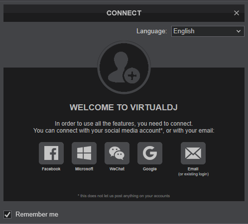
Once VirtualDJ is launched, a Connect Window will appear to choose one of the available ways to login.
A Pro Infinity, a Pro Subscription or a PLUS License is required to use the Hercules DJControl Inpulse 500. Without any of the above Licenses, the controller will operate for 10 minutes each time you restart VirtualDJ.
http://www.virtualdj.com/buy/index.html
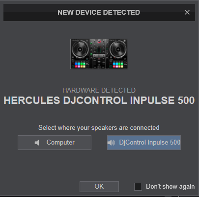
 A detection window will appear next verifying the proper connection.
Click on the DJ Control Inpulse 500 button to allow VirtualDJ to auto-create the pre-defined audio configuration. Speakers need to be connected to the rear panel of the device.
Click on "Computer" button if you don't have speakers to connect and need to output sound from your computer's built on sound card.
Click to OK
The unit is now
ready to operate.
MIDI Operation.
The unit should be visible in the MAPPING tab of Config and the “
factory default” available/selected from the Mappings drop-down list. The factory default Mapping offers the functions described in this Manual, however those can be adjusted to your needs via VDJ Script actions.
Find more details at
http://www.virtualdj.com/wiki/VDJ8script.html 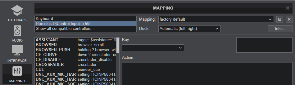
AUDIO Setup
The unit has a pre-defined Audio configuration and a special button in the AUDIO tab of Config to provide that. The default audio configuration requires speakers to be connected at the rear-side
Master RCA or TRS sockets and headphones at the front panel 1/4" or 1/8" socket.
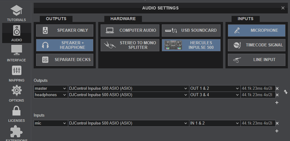
Refer to VirtualDJ Manual for alternative audio configurations
http://www.virtualdj.com/manuals/virtualdj8/settings/audiosetup.htmlFor further software settings please refer to the User Guide of VirtualDJ.
http://www.virtualdj.com/manuals/virtualdj8/index.html
MIXER & BROWSER CONTROLS
KEY
ACTION
SHIFT (SECONDARY) ACTION
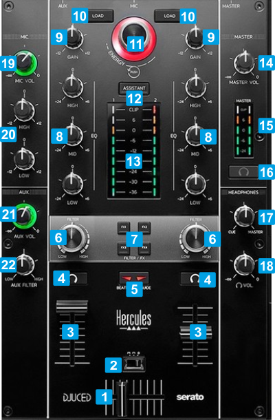
1 CROSSFADERWhen on far left position, only sound from the left deck will be heard from the Master Output. When at far right position, only the sound of the right deck will be heard from the Master Output. In all other positions, the audio signals from left/right decks will be blend. 2 CF CURVESelect a mode (curve) for the Crossfader between Smooth, Scratch and Disabled. 3 VOLUMEAdjust the Volume of the Left/Right deck 4 PFLUse these buttons to send the pre-fader audio signal of the Left/Right deck to the Headphones channel for pre-listening (connection at the front side). 5 BEATMATCH GUIDEWhen enabled, several assistant leds on the Decks will guide you for a perfect beat-match 6 FILTERApply the selected Color FX to Left/Right deck. No ColorFX is applied (off) when the knob is at the center/middle position 7 COLOR FX1-FX4Use these buttons to select and enable/disable a Color FX. When a Color FX is selected (led solid), press again to activate.
FX1 : High-Low Pass Filter
FX2 : Echo ColorFX
FX3 : Pitch Color FX
FX4 : Noise Color FX 8 EQ HIGH/MID/LOW3-Band Equalizer. Use these knobs to cut/boost the frequencies of the Low(Bass) / Mid (Middle)/ High (Treble) Equalizer Band No adjustment is made when the knob is at the middle/center position 9 GAINUse these knobs to adjust the pre-fader output level of the Left/Right deck When the knob is at the middle/center position, the track will be at zero dB level (or any other value set in VirtualDJ Options) 10 LOADLoad the selected track from the Browser to the Left/Right deck. Double/fast-press these buttons to clone the track from the opposite deck to the Left/Right deck.Unload the deck 11 BROWSERScroll through the folders or tracks, depending on the focused Browser List.
Push to toggle focus between the Folders and Songs Lists. When focus is on the Folders List, push and hold dial down (for about 1 second) to open/close sub-folders.
The RGB led of this dial indicates the Key compatibility of the selected track based on the Deck that is currently playing.
Green : Full compatible
Blue : Semi-compatible
White : not compatibleTurn to set focus to Sideview and cycle through its views (Automix, Sidelist, Karaoke, Sampler and Shortcuts).
Push to toggle Browser focus between Sideview and Song list12 ASSISTANTUse this button to select the Recommendations folder and get online suggestions based on the currently playing track. Press again to select the previously working folder. 13 VU METERSIndicate the pre-fader level of the Left/Right deck 14 * MASTER VOLAdjust the level of the Master Output (connection at the rear panel). 15 * MASTER VU METERSIndicate the overall output level on the Master Output of the device. 16 * MASTER PFLSends the audio signal from the Master Output to the Headphones channel. Hardware operation, not visible in GUI or controlled from VirtualDJ 17 * HEADPHONES MIXBlends the signal from the Deck or Master PFL and the Master Output in Headphones. 18 * HEADPHONES VOLAdjusts the level of the Headphones Output (connection at the front panel). 19 ** MIC VOLAdjusts the level of the Microphone Input (connection at the rear panel). 20 ** MIC EQ2-Band Equalizer. Adjust the High/Low frequencies of the Microphone Input signal (connection at the rear panel). 21 ** AUX VOLAdjusts the level of the AUX Input (connection at the rear panel). 22 ** AUX FILTERApply a High/Low pass Filter to the AUX input. Notes* These buttons/knobs offer Hardware operations, but may reflect their movements and status on the VirtualDJ GUI (fake mode) and should not be assigned to any other function.
** These knobs offer Hardware operations and should not be assigned to any VDJ script action. They apply to the Microphone/AUX inputs of the device, before sent to Master or USB Audio Interface.
DECK CONTROLS
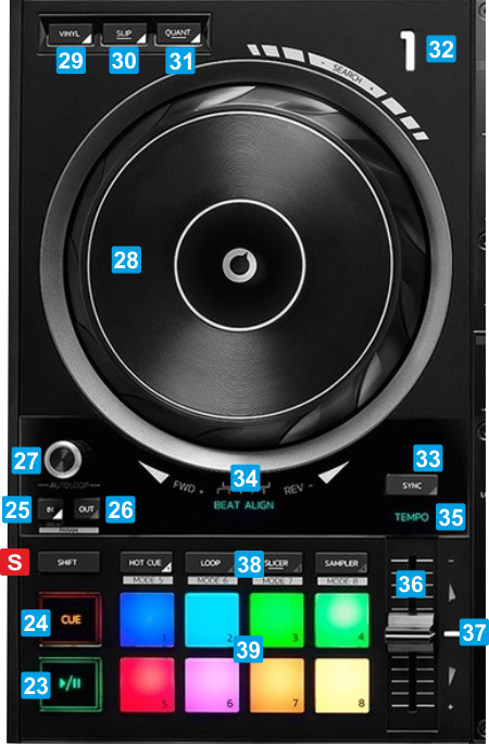 S SHIFTPress this button down to access secondary actions as described in the SHIFT ACTION column
KEY
ACTION
SHIFT (SECONDARY) ACTION
23 PLAYPlay/Pause the track loaded to left/right deckPlay-stutter track. When pressed, track will resume playing from the previously stopped position24 CUESets current position as Temporary Cue point.
Preview track when paused while button is pressed
Jumps and stops to the Cue point when playingReturns to the beginning of the track25 LOOP INWhen not in loop, press to set current position as the beginning of a manual loop. Press and hold this button for more than 1 second to turn a 4 beats auto-loop on/off.
When in loop, press to enable/disable the Jogwheel Loop In Adjust mode and then use the Jogwheel to fine-adjust the Entry point of the loop.Decrease the Parameter 1 (if available) of the current Pads mode.26 LOOP OUTWhen not in loop, press to set current position as the end of a manual loop.
When in loop, press to enable/disable the Jogwheel Loop Out Adjust mode and then use the Jogwheel to fine-adjust the Exit point of the loop.Increase the Parameter 1 (if available) of the current Pads mode27 LOOPTurn to half/double the size of the loop. Push to turn the loop on/off.If in Loop, turn to move the loop backwards/forward in time by 1 beat.28 JOGWHEELTouch-sensitive jogwheel for scratching or bending (temporary speed up/down tempo) the track, depending on the Vinyl mode.Fast seek (search) track forward/backwards29 VINYLEnable/disable Vinyl mode. When enabled, use the upper/top surface of the jogwheel to scratch and the outer to bend. When disabled, the entire surface (upper and outer) of the jogwheel will be used for bending. 30 SLIPEnable/disable Slip mode on the Left/Right deck. When enabled (its led is turned on) several functions, such as scratching, loops and hotcues will be performed temporary and when finished (released), the track will resume from the position it would have been if the action was never triggered. 31 QUANTIZEEnable/disable Quantize mode on the Left/Right deck. When enabled (its led is turned on) several functions, such as loop and hotcues will be snapped to the nearest beat (or other value based on the globalQuantize VirtualDJ setting) 32 DECK NBThe LED will indicate if the Deck is audible in Master 33 SYNCMatch BPM and Beat Phase with the opposite deckSmooth pitch reset. When pressed track will gradually get its original tempo34 BEAT ALIGNThese leds indicate the direction the jogwheel needs to be moved to, in order its beat-grid to match with the opposite deck. Leds will operate if:
- the BeatMatch Guide button [5] is turned on
- the Deck is not the Master-Deck (deck that is playing out live - on air)
- the deck is not playing 35 TEMPO LEDThe LED indicates if the Track's tempo matches the value of the opposite Deck and will be offered if the BeatMatch Guide button [5] is turned on. 36 TEMPOAdjust the tempo of the loaded track When in middle position (white led is turned on), the track plays at its original speed.. 37 TEMPO ASSISTANT LEDsWhen the BeatMatch Guide button [5] is enabled, a blinking LED indicates the direction the Tempo fader needs to be moved in order the track to get the same BPM as the one of the opposite Deck. 38 PAD MODESSet the 8 Pads to one of the available 4 primary modes. See Pads page for further details.Set the 8 Pads to one of the 4 secondary modes. See Pads page for further details. 39 PADSThese performance pads offer different functionality depending on the selected Pads mode See Pads page for further details.These buttons offer different functionality depending on the selected Pads mode See Pads page for further details
PERFORMANCE PADS
KEY
ACTION
SHIFT ACTION
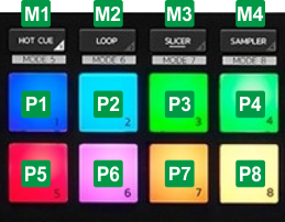
M1 HOTCUESet Pads to Hotcues mode (led will be turned on solid)Set Pads to KeyCue mode (led will be flashing)M2 ROLLSet Pads to Roll mode (led will be turned on solid)Set Pads to FX mode (led will be flashing)M3 SLICERSet Pads to Slicer mode (led will be turned on solid)Set Pads to Scratch mode (led will be flashing)M4 SAMPLERSet Pads to Sampler mode (led will be turned on solid)Set the 8 Pads to BeatJump mode (led will be flashing)HOTCUE MODE
Press the HOTCUE mode button [M1] to set the Pads to Hotcue mode. The Hotcue Pads page will be also displayed on the GUI of VirtualDJ, reflecting the operation of the 8 Pads. 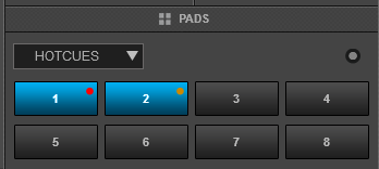
Hotcues Pads Page KEY
ACTION
SHIFT (SECONDARY) ACTION
PADS 1-8Assigns current track's position to Hotcue 1 to 8 or jumps to its position if already setDelete the assigned Hotcue 1 to 8
LOOP MODE
Press the LOOP mode button [M2] to set the Pads to Loop Roll mode. The Loop Roll Pads page will be also displayed on the GUI of VirtualDJ, reflecting the operation of the 8 Pads. 
Loop Roll Pads Page KEY
ACTION
SHIFT (SECONDARY) ACTION
PADS 1-8Press and hold a Pad to trigger a Loop Roll of a pre-defined size in beats.. The track will resume playing from the position it would have been if the loop roll was never triggered. Same action
SLICER MODE
Press the SLICER mode button [M3] to set the Pads to Slicer mode. The Slicer Pads page will be also displayed on the GUI of VirtualDJ, reflecting the operation of the 8 Pads. 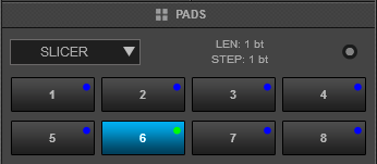
Slicer Pads Page KEY
ACTION
SHIFT (SECONDARY) ACTION
PADS 1-8Each Pad represents a slice of the beat-grid pattern (1 beat or other size defined from the 1st Parameter of the Slicer Pads page). Press and hold a Pad to repeat-loop a part of this slice (depending on the 2nd Parameter value). The track will resume playing from the position it would have been if the slicer pad was never triggered. Same action, with the difference that the slice is memorized.
SAMPLER MODE
Press the SAMPLER mode button [M4] to set the Pads to Sampler mode. The Sampler Pads page will be also displayed on the GUI of VirtualDJ, reflecting the operation of the 8 Pads. 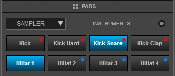
Sampler Pads Page KEY
ACTION
SHIFT (SECONDARY) ACTION
PADS 1-8Press Pad 1 to 8 to trigger a Sample (1 to 8) of the selected Sampler Bank (1st Parameter of Sampler Pads page) The sample will be triggered depending on the selected Trigger Sampler mode (2nd Parameter of the Sampler Pads page) Stop the playing sample. Useful when the Stutter or Un-mute trigger mode is selected*Note: If the selected Sampler Bank has less than 9 samples, both sides of the Pads will trigger the same samples. If the selected Sampler Bank has more than 8 samples, the left side Pads will trigger Samples 1 to 8 and the right side Pads will trigger Samples 9 to 16.
MODE 5 - KEYCUE
Hold SHIFT and then press the HOTCUE mode button [M1] to set the Pads to KeyCue mode. The KeyCue Pads page will be also displayed on the GUI of VirtualDJ, reflecting the operation of the 8 Pads. 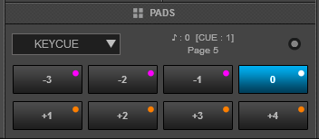
KeyCue Pads Page KEY
ACTION
SHIFT (SECONDARY) ACTION
PADS 1-8Each Pad jumps to the currently selected Hotcue (or temporary CUE if no Hotcue is assigned) and plays and changes its musical key by a semitone value designated from the Pad's text as shown on GUI. Different values can be used by selecting a different page (2nd Parameter of the KeyCue Pads page)Select a Hotcue for the KeyCue pads to apply to.
MODE 6 - FX MODE
Hold
SHIFT down and then press the LOOP mode button [M2] to set the Pads to FX mode (led will be flashing). In this mode, the Inpulse 500 can operate in 2 modes, depending on the
PadFXMode setting (from VirtualDJ Settings->OPTIONS tab).
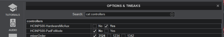 When set to No (default), the Pads will be assigned to INP FX page, and will offer controls for VirtualDJ Effects. In this mode the Page can be assigned to any of the available VirtualDJ Pad pages.
*Note: This special Pads Page will be available to select, only if the Inpulse 500 is connected.[
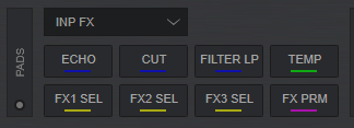
Inpulse500 FX Pads Page KEY
ACTION
SHIFT (SECONDARY) ACTION
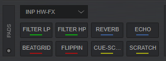
PAD 1Trigger the Effect of FX Slot 1 PAD 2Trigger the Effect of FX Slot 2 PAD 3Trigger the Effect of FX Slot 3 PAD 4When enabled, Pads 1 to 3 will trigger their assigned Effects while Pads are held down (temporary mode)Load the Effects of FX Bank 1 to FX Slots 1 to 3. Hold down for more than 1 second to save the Effects assigned to FX Slots 1 to 3 to FX Bank 1. PAD 5Select the next available Effect for FX Slot 1 PAD 6Select the next available Effect for FX Slot 2 PAD 7Select the next available Effect for FX Slot 3 PAD 8Enable/disable the FX Param mode. When enabled and the INP FX Pads page is selected, use the LOOP Encoder to control the 1st Parameters of all the Effects in Slots 1 to 3 (or with SHIFT down for Parameter 2)Load the Effects of FX Bank 2 to FX Slots 1 to 3. Hold down for more than 1 second to save the Effects assigned to FX Slots 1 to 3 to FX Bank 2. When set to Yes, the Pads will be assigned to INP HW FX page, and will offer mostly hardware operations. In this mode the Page cannot be assigned to any of the available VirtualDJ Pad pages.
The functionality of the Pads in this mode is mostly hard-coded in the Inpulse firmware and most of it cannot be changed. As a result of this hardware functionality, the Pads on the GUI do not offer any functionality if triggered from GUI, they just offer an aid showing the selected FX mode and an idea of what each Hardware pad does.
*Note: This special Pads Page will be available to select, only if the Inpulse 500 is connected.
Inpulse500 HW FX Pads Page KEY
ACTION
SHIFT (SECONDARY) ACTION
PAD 1Press and hold Pad 1 to trigger the Filter LP Effect. The pad also controls the 1st Parameter of the LP Filter effect, starting from the zero value and gradually increasing to the maximum, as long as the pad is pressed. Effect is turned on when the pad is released (momentary) No function is assignedPAD 2Press and hold Pad 2 to trigger the Filter HP Effect. The pad also controls the 1st Parameter of the HP Filter effect, starting from the zero value and gradually increasing to the maximum, as long as the pad is pressed. Effect is turned on when the pad is released (momentary) No function is assignedPAD 3Press Pad 3 to trigger the Reverb * Effect. The pad also assign the 1st Parameter of the Reverb effect to a certain value, and gradually fast-decreases deck's Volume to the minimum. Effect is turned on when the pad is pressed again (toggle)No function is assignedPAD 4Press Pad 4 to trigger the Echo * Effect. The pad also assign the 1st Parameter of the Echo effect to a certain value, and gradually fast-decreases deck's Volume to the minimum. Effect is turned on when the pad is pressed again (toggle)No function is assignedPAD 5Press and hold Pad 5 to trigger the Beat Grid Effect. The Effect is turned off when the pad is released (momentary)No function is assigned PAD 6Press and hold Pad 6 to trigger the Flippin Double Effect. The Effect is turned off when the pad is released (momentary)No function is assigned PAD 7Press and hold Pad 7 to perform a "Baby" Scratch effect at the current position. The Scratch is turned off when the pad is released (momentary)No function is assignedPAD 8Press and hold Pad 8 to jump at the 1st assigned Hotcue and perform a "Baby" Scratch effect from that position. The Scratch is turned off when the pad is released (momentary)No function is assigned Note *:
For best results on the Reverb and Echo Effects, it is advised to enable the Post Fader Effects setting (from VirtualDJ Settings->Options tab->fxProcessing setting to Post-fader). This will allow these Effects to continue trailing for a while, when the Volume fader is moved to the minimum position
MODE 7 - SCRATCH
Hold SHIFT down and then press the SLICER mode button [M3] to set the Pads to Scratch mode. The Scratch Pads page will be also displayed on the GUI of VirtualDJ, reflecting the operation of the 8 Pads.
Scratch Pads Page KEY
ACTION
SHIFT (SECONDARY) ACTION
PADS 1-8Each Pad performs a scratch routine while pressed or quickly releasedOpens the Scratch DNA Editor to edit the scratch routine.
MODE 8 - BEATJUMP
Hold SHIFT down and then press the the SAMPLER mode button [M4] to set the Pads to BeatJump mode. The BeatJump Pads page will be also displayed on the GUI of VirtualDJ, reflecting the operation of the 8 Pads.
BeatJump Pads Page KEY
ACTION
SHIFT (SECONDARY) ACTION
PADS 1-8Each Pad moves the track forward/backwards by the value in beats designated by the Pad's text on GUI. Different beat values can be applied by selecting a different page (1st Parameter of the BeatJump Pads page)Same action
FRONT & REAR PANELS
 Hercules DJControl Inpulse 500 - Rear panel 40 MASTER OUTUnbalanced Master Output. Connect your amplifier or amplified speakers using TRS cables41 MASTER OUTSecondary Unbalanced Master Output. Connect your amplifier or amplified speakers using RCA cables42 MIC INConnect your Microphone using a TRS mono cable43 AUX INConnect an auxiliary media source using RCA cables.44 AUX INConnect an auxiliary media source using 1/8" cable45 USBConnect Inpulse 500 with a USB port of your computer, using a standard Type A/B USB cable.46 HERCULES ADD-ONNot used
  Hercules DJControl Inpulse 500 - Front panel 47 HEADPHONESConnect your Headphones using a 1/4" or 1/8" cable-adapter.
INPUTS & SETTINGS
AUX/MIC Inputs
The Hercules DJControl Inpulse 500 offers a AUX and a MIC Input (connections at the rear panel) to connect an auxiliary media source and/or a Microphone respectively. The signal of both of these inputs can be routed directly to the Master Output or to the Input of the USB Audio Interface.
The selection can be done via the VirtualDJ Settings->OPTIONS tab->Controllers category and will be saved across sessions.
Note that when closing VirtualDJ, the inputs will be automatically routed to Master Output.

When the
HardwareMicAux setting is set to
Yes (default value), the MIC and AUX Inputs are routed directly to the Master Output. In this case, the signal of these inputs is not recorded along with your mix, and the MIC and/or LINE/AUX buttons in VirtualDJ GUI will not affect the inputs.
When the
HardwareMicAux setting is set to
No , the MIC and AUX Inputs are routed to the Input of the USB Audio interface of the device. In this case, the signal of these inputs is recorded along with your mix, and the MIC and/or LINE/AUX buttons in VirtualDJ GUI will affect the inputs.
Note that regardless the
HardwareMicAux setting, the top-panel AUX/MIC controls (Equalizer, Level, Filter) will still apply to the signal of these inputs, before sent to either Master Output or USB Audio Interface Input.
FEET Back-lighting
Hold down Pads 1 ,5 on left side and Pads 4, 8 on right side for about 3 seconds to turn on/off the Bottom-Feet Backlight leds of the Hercules Inpulse 500.
For further Technical features and specifications, visit Hercules DJ CONTROL INPULSE 500
Product's Page
 Hardware Integration Department 2020 - ATOMIX PRODUCTIONS Reproduction of this manual in full or in part without written permission from Atomix Productions is prohibited.